Product Description
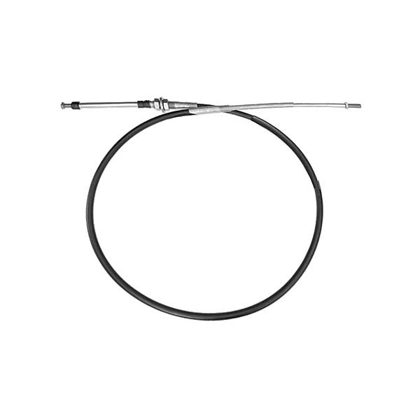
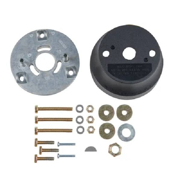
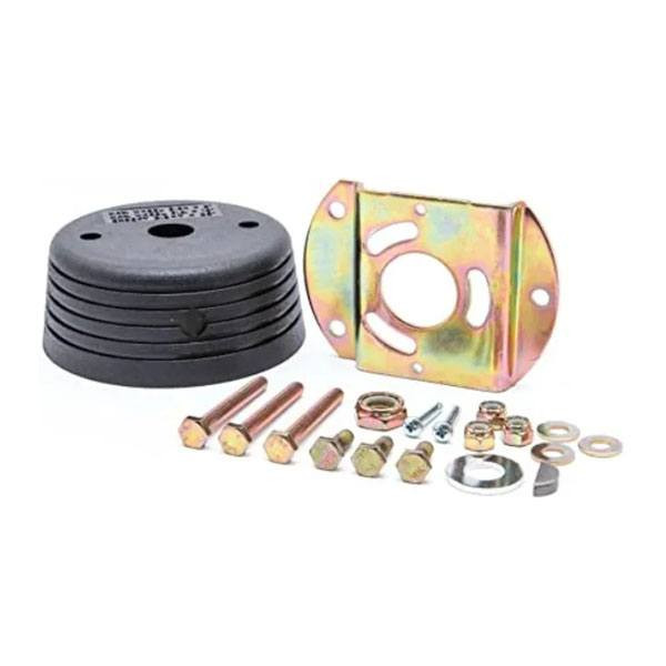
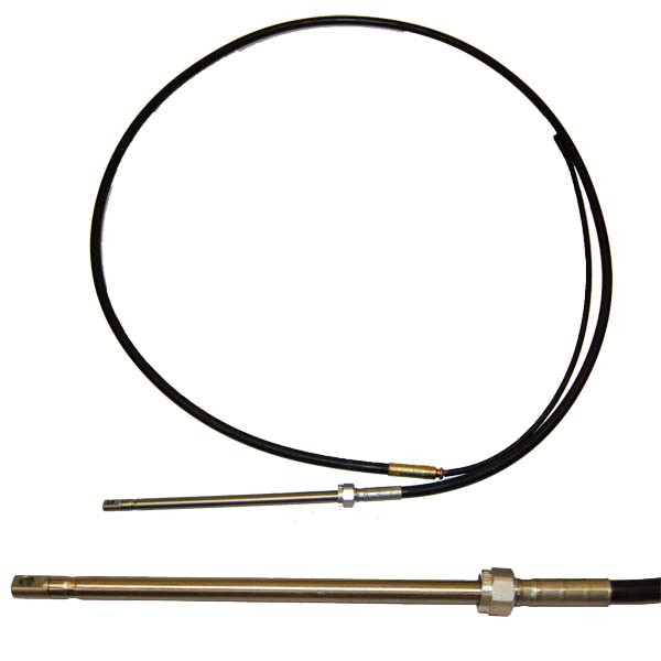
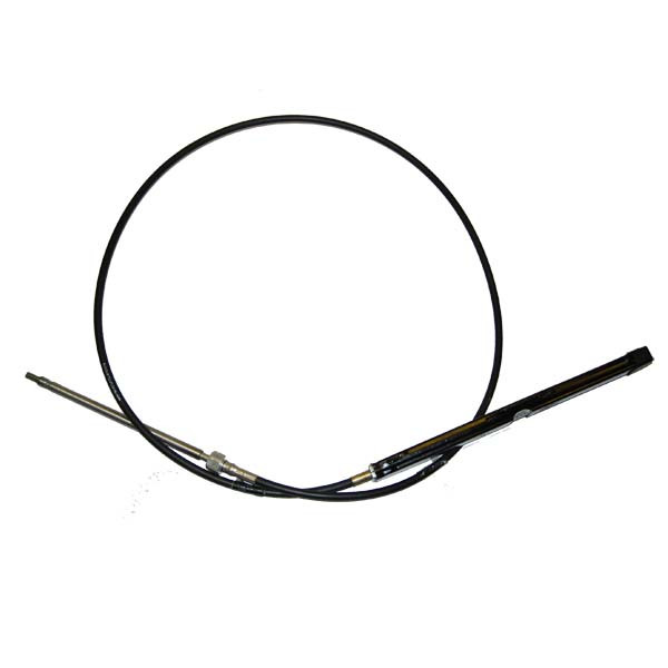
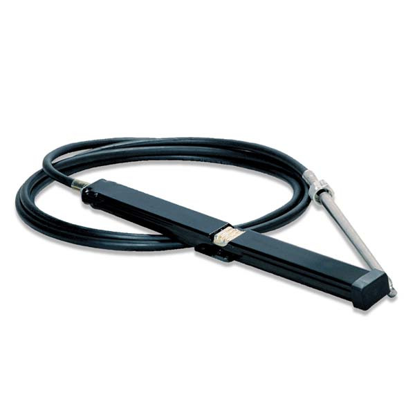
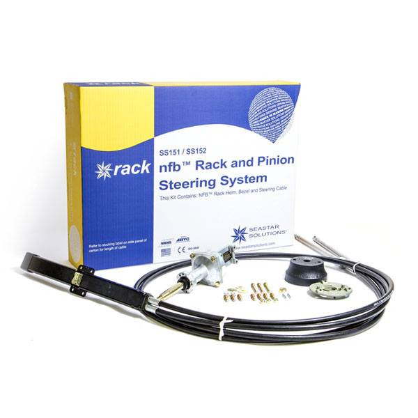
NFB Pro Rack Outboard Dual Cable Steering SystemSupersedes: TEL-SS14816Owners of high-speed and racing boats need a reliable outboard dual cable steering system to achieve optimal performance. For the high-performance boater, we recommend the Teleflex dual steering system. The No FeedBack technology combines precision with the control associated with a dual cable rack and pinion system. The Pro Rack is designed for high performance hulls and motors. These boats are normally engine flutter-prone, experience instability, or just require an extra margin of control at the helm. This dual steering system is designed as a drop-in replacement for Teleflex's "The Rack".Applications:The Teleflex dual steering systems are suitable for single-station, high performance boats with single, non-power-assisted outboards (up to V-6). Use NFB Rack with up to 16" steering wheels.Features: Patented No FeedBack Steering mechanism.; Dual Cables minimize lost motion in system.; Precise feel of 4 turns from lock-to-lock.; Minimal clutch free play.; Standard 3/4" round tapered steering shaft.; Stainless steel cable output ends.; Fast, easy installation; back mount design allows quick placement in dash PLUS mounting hardware fits industry-standard Teleflex and Morse rack holes.; Kits include: cable, helm, 90 bezel and hardware.; Meets A.B.Y.C. standards.; Meets N.M.M.A. certification requirements; Note: Product images include both old and new packagingHow to Measure Steering Cables:Replacement of Existing Cable: If possible, find the part number stamped on the plastic jacket of the old cable. If you removed the old cable, measure for the replacement cable as follows:For Rack Steering Cable Replacement, Measure Existing Cable as follows: Measure plastic cable jacket ("Y" dimension shown in above drawing) in inches, add 30a ^2, and round up to next foot. Order that length cable.New Installation: Measure cable routing path from wheel center line to engine connection, as follows: A = Center line of wheel to gunwale (or deck, if routed downward); B = Dash to transom; C = Gunwale to centerline of cable connection at centered tiller.; For Cable Installations through the Engine Tilt Tube: Add A, B & C + 6a ^2, then round up to the next foot. Order that length cable.For Cables Mounted to Transom, Splashwell or Stringer: Add A, B & C, then subtract 6a ^2 and round up to the next foot. Order that length cable.TYPICAL SINGLE STATION ROUTING A single-cable, starboard drive push-pull mechanical cable system is shown in this diagram. If your mechanical system is different than the one depicted and/or you have any questions about mechanical steering after reviewing this guide, please contact Teleflex (Mechanical) Technical Service at (610)-495-7011 or www.teleflexmarine.comCable routings (such as those found on pontoon boats) may vary from this drawing. Confirm length by laying a garden hose or similar object) along cable path and measure run from wheel to engine connection point.

NFB Pro Rack Outboard Dual Cable Steering System
$680.09
In Stock
at Wholesale Marine
Price verified 1d ago
 Amazon
 eBay
eBay
Product Details
Brand
Dometic