Product Description
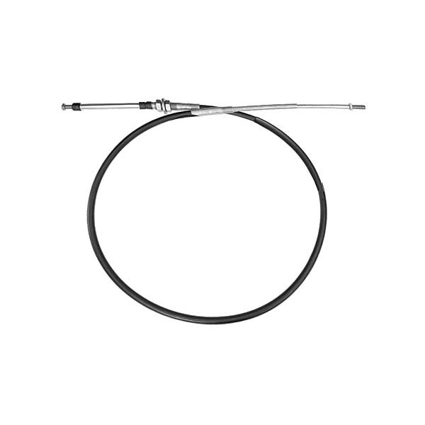
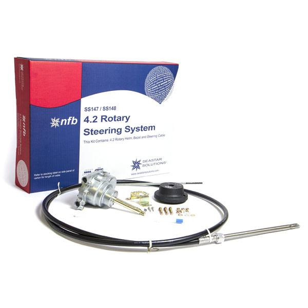
NFB 4.2 Mechanical Rotary Steering SystemPatented No FeedBack Steering Control for about the cost of an old-fashioned steering replacement. With the advantage of 4.2 turns lock-to-lock and the patented No Feedback steering to lock out steering load, 4.2 Rotary NFB Steering is the ideal single-cable system for most non-power-steered boats. The helm is a drop-in replacement for current generation Safe-T with no dash modifications required.Applications:NFB 4.2 single-cable systems are suitable for most single-station boats with a single non-power-assisted outboard engine up to V-6 and minimal engine flutter or steering instability. 4.2 Accepts steering wheels up to 16" diameter.Use dual cable system for boats with engine flutter or steering instability.Replaces nearly all Teleflex safe-T steering systems without dash modifications.Features: Patented No Feedback Steering mechanism.; Comfortable 4.2 turns from lock-to-lock; Minimal clutch free play.; Standard 3/4" round tapered steering shaft.; Stainless steel cable output ends.; Fast, easy installation: uses Quick Connect (QC) steering cable.; Kits include: cable, helm, 90 degree bezel and hardware.; Meets A.B.Y.C. standards; Meets N.M.M.A. certification requirements.; *Note: Product images show both new and old packagingHow to Measure Steering Cables "Measure Twice. Order Once."Replacement of Existing Cable: If possible, find the part number stamped on the plastic jacket of the old cable. If you removed the old cable, measure for the replacement cable as follows:For Rotary Steering Cable Replacement, Measure Existing Cable as follows: Measure plastic cable jacket ("Y" dimension, shown in above drawing) in inches, add 18a ^2, and round up to next foot. Order that length cable.New Installation: Measure cable routing path from wheel center line to engine connection, as follows: A = Center line of wheel to gunwale (or deck, if routed downward), B = Dash to transom, C = Gunwale to centerline of cable connection at centered tiller.For Cable Installations through the Engine Tilt Tube: Add A, B & C + 6a ^2, then round up to the next foot. Order that length cable.For Cables Mounted to Transom, Splashwell or Stringer: Add A, B & C, then subtract 6a ^2 and round up to the next foot. Order that length cable.TYPICAL SINGLE STATION ROUTINGA single-cable, starboard drive push-pull mechanical cable system is shown in this diagram. If your mechanical system is different than the one depicted and/or you have any questions about mechanical steering after reviewing this guide, please contact Teleflex (Mechanical) Technical Service at (610)-495-7011 or www.teleflexmarine.comCable routings (such as those found on pontoon boats) may vary from this drawing. Confirm length by laying a garden hose or similar object) along cable path and measure run from wheel to engine connection point.

NFB 4.2 Mechanical Rotary Steering System
$405.49
In Stock
at Wholesale Marine
Price checked 14 days ago
 Amazon
 eBay
eBay
Product Details
Brand
Dometic





))/4612992.json)

))/4612992.json?$BPSMkt_ProductFeeds$&extend=380,380,380,380)